.jpg)
Building your own inexpensive, lightweight, septum feed
This is not a step by step construction article with all dimensional specifications. It's more of an idea of what you can go to build a lightweight septum feed. Where you drill the holds, how many holes you drill and what you use to attach the parts together is up to you once you've read though the basic construction principles. It's a proof of concept, which means that if you try building feeds like these, you won't be wasting your time. They will work - and it's up to you to make them work well!
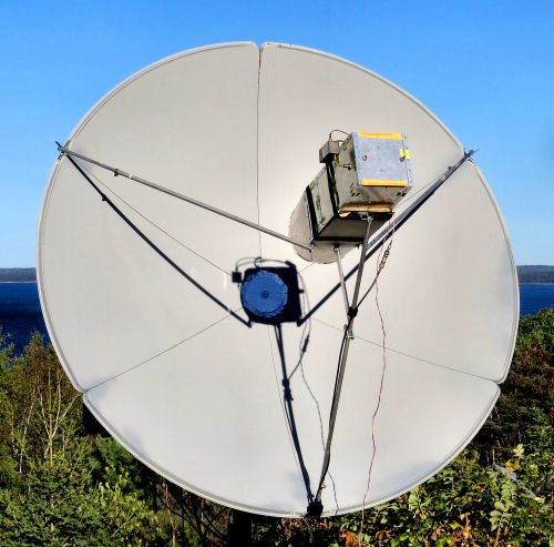
Following my "discovery" of the 1.5m cooker dish, the next step was to come up with an efficient feed for it. Well, it turns out it's not hard to build a cheap (<$50) lightweight septum feed for 23cm. It takes some time and effort, but need not require any sheet metal bending or welding or any other machine shop facilities. Basic tools required would be something like:
- Hand drill (a drill stand preferred)
- Hacksaw(s)
- File(s)
- Set of the right size drill bits
- A tap (probably #2-56)
- Sharp utility knife
- Soldering iron
- Small Vise
I built three different feeds. One was made from copper foil coated wood. one was made from 1mm thick aluminum sheet and one was made from 1/4" mesh sheet.
Basic design principles
A typical septum feed consists of a section of square waveguide, approximately 150mm (6") square, with a solid plate at one end and a septum running along the center from the plate at the rear to the open end of the guide. The septum and waveguide must be made of conductive material. Copper or aluminum (or brass) are all file. Copper and brass are heavy though and aluminum can't be easily soldered, so each material has advantages and disadvantages. Galvanized steel might work, assuming a thick enough layer of zinc, but it's not an ideal choice.
Since copper sheet is expensive and heavy, I chose to use wooden boards (3mm thick) with adhesive copper foil attached to all internal surfaces. For the aluminum feed I chose 1mm thick sheet because it's light, it's cheap, and it's easily obtainable. For the mesh feed I chose 1/4" galvanized steel 1/4" mesh hardware cloth.
Since the idea is no bending. minimum sawing and no welding, the square waveguide was made from suitably treated and sized panels arranged into a square tube, In the case of copper covered wood, the internal seams could be easily soldered together. However to add strength and rigidity, thing 1/2" aluminum angle was added externally on all four seams. In the case of the aluminum feed, the external aluminum angle was used to both keep everything aligned and to provide electrical conductivity between the aluminum sheets. The mesh feed was easily bent into shape and seams were "sewn" togther with copper wire and (maybe) also soldered in places
With a stepped septum the feeds are approximately 6"x6"x16". The mech feed used a slop septum and was about 14" long.
Wood with Copper foild
Feed weight about 950g
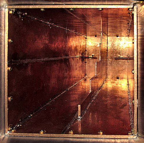
Inside of fed showing septum
Building a feed out of wood may sound like an odd idea, but wood isn't a bad material for construction. Houses are made of wood, boats are often made of wood, even some cars and airplanes are made of wood. The problems with wood are (a) it's not conductive and (b) it can rot, bend and warp if not treated properly. The advantage of wood is that it's relativly cheap, easy to obtain, it can be very light, and it is very easy to work with.
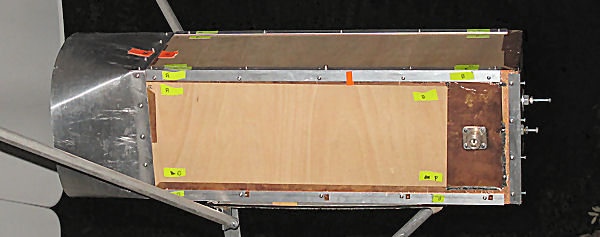
Feed shown with short square to round extension
Wood can be made conductive by applying a thin sheet of copper foil to the surface. Skin depth at 23cm is about 1.7 microns in copper. For good conduction you need about 5 skin depths of material. 17 micron thick copper sheet (10 skin depths) is fairly easy to find (though don't believe spec sheets on Chinese based products). It's available with "conductive" adhesive, but it's not conductive enough and the conduction of the adhesive isn't stable enough for this purpose. Any copper sheet to copper sheet connections need to be soldered. I used this 4" wide copper foil strip. Two 18" lengths of this will over one side of a 16" x 6" panel with good wrap around at the edges.
Before applying copper foil, the wood needs to be treated with MULTIPLE layers of something which will protect it from the environment. Something like Spar Varnish can be used. This prevents UV damage, water penetration etc. Spar varnish is an exterior-grade, flexible, and elastic wood finish, originally developed to coat the wooden masts and rigging (spars) of sailing ships. The better you protest the wood (all surfaces and edges), the less likely it is to suffer from environmental (mostly water) damage. I would note that this construction method may not be the best for long-term unprotected outdoor use. I have not tested how durable it is outdoors in bad weather. That's a decision you have to make if you choose this method of construction. I have used it this feed for a few hours in light rain, and it's often wet from dew formation when I bring it inside. So far there has been no sign or damage or warping. If left outdoors for very long I would certainly put something around it to protect it from the sun and rain.
3mm thick wood (basewood)is easily available in 12" x 16" sheets (e.g from Amazon),so if you split it along the length you end up with 16" x 6" sheets, 4 of which can be used to fabricate suitable square waveguide. You don't have to saw it. This wood can be cut using multiple scoring along a line with a sharp utility knife. This makes a very accurate, very smooth cut.
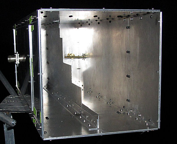
Aluminum
Feed weight around 1150gm
It's hard to find 16" x 6" aluminum plates at a low price, but 12" x 6" (probably really 300mm x 150mm) is easy to find and cheap. You can just cut one of these pieces in half and then splice it onto the end of a full sheet to make a 16" x 6" panel. You do not need to saw 1mm aluminum sheet to cut it. If you score it deeply (multiple strokes) in both sides of a line, then gently bend it back and forth along the line, it will break cleanly, leaving a straight, accurate edge.
You can then make square waveguide with an ID of 149mm by overlapping these panels and attaching then together with thin (e.g. 0.05") 1/2" aluminum angle (Home Depot stocks it) running along the overlapping edges. Multiple nuts and bolts, or bolts and tapped holes will be required. The more the better, but there's a limit to most people's tolerance for drilling (and tapping) holes. Over the 16" length it would be good to have maybe 8 fasteners of some sort. Maybe fewer would be OK, I don't know. So for the square waveguide that's a total of at least 64 screws.
If, on the other hand, you don't care about weight or cost and want to build your own feed, then the construction method described by KL6M and which I based my own feed on (see KA1GT septum feed works very well. The feed is strong but heavy and the component materials cut to size are pretty expensive (maybe $300 today). It also involves sawing the septum out of 1/4" thick aluminum plate, which though not all that difficult, is time (and energy) consuming!
Mesh
Feed Weight around 250g
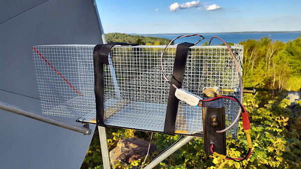
Metal mesh with small enough holes acts like a sheet of metal at RF wavelengths. "Small" holes refers to holes that are 1/20 th the wavelength or less. At 23cm, 6mm or 1/4" holes are about 1/40 wavelengths, so 1/4" or 6mm mesh acts pretty much like a solid shoot of metal as far as RF in concerned. That's why you can use a dish with a mesh surface rather then a solid surface without suffering additional loss. The only readily available mesh material is usually galvanized steel, which is steel with a zinc coating. As long as the zinc is thicker than about 3 microns and you need at least 5 skin depths to ensure good performance. 99+% of the power travels in the first 5 skin depths. So as long as the zinc is at least 15 think, the RF will never see the ferromagnetic steel (which would be quite lossy. Since mesh is very easily cut and belt, forming it into the right shapes is easy. It can be sewn together with copper wires to get conduction between seams. With care it can sometimes be soldered too.
Basic square waveguide structure
The basic structure of the copper foil and aluminum feeds is as shown below"
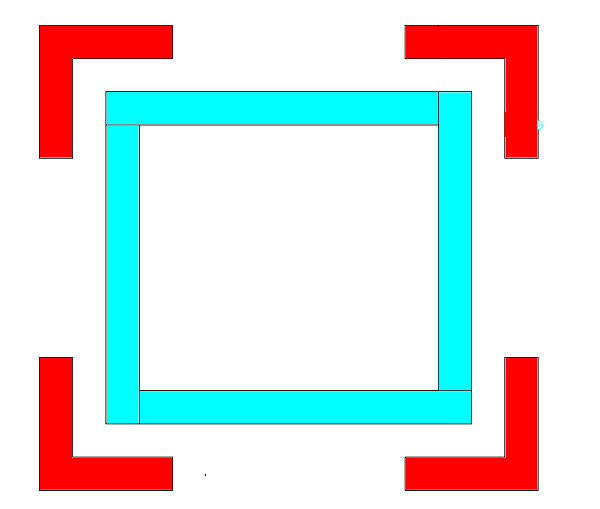
The 4 sides of the feed are arranged as shown in blue. They overlap to form an internal and external square. The ID is (the with of each side) - (the thickness of the sheet). So if the individual panels are 150mm wide and they are 1mm thigh, the ID is 149mm square.
The red corners are the aluminum angle. Obviously this sketch is not to scale, it's just to show the basic layout of the parts. The aluminum angle is bolted to the sides either using screws and nuts or screws and tapped holes. You can tap #2-56 holes in 1mm thick aluminum. There aren't many threads (about 2 turns) and aluminum is quite soft, so that limits the torque you can apply to screws in tapped holes. You can actually tap holes in 3mm wood which will hold #2-56 screws, but again, you should not try to make them too tight. The good thing is that if you do strip out the tapped holes, you can always add a nut and tighten things up again.
Ideally screws and nuts (anything inside the waveguide) should be brass. If you can't find brass, second best is stainless steel. Using anything feromagnetic (like black oxide steel) on the inside of the waveguide would be best avoided, though you can probably get away with it if penetration into the guide is small. I found that Zoro.com is a good place to find #2-56 screws and nuts in bulk. Depending on the material, head style and length, you can get 100 screws, nuts or washers for just a few dollars.
The construction of the corners of the copper clad wooden feed is as shown in more detail below:
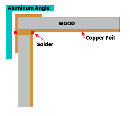
The copper foil wraps around the panels and can be soldered on the inside of the waveguide seams and/or on the outside. It can be difficult (but is not impossible) to solder on the rear plate from the inside, so in that case soldering on the outside is probably easier.
Septum
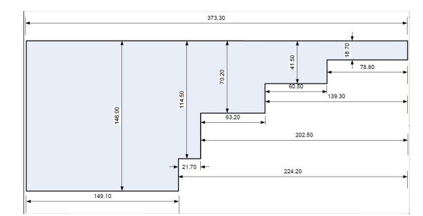
KL6M septum dimensions for 146mm ID square waveguide
I went with a stepped septum rather than a slant septum because it may perform a little better in some respects. It's slightly longer and slightly more difficult to cut out accurately, but that's not a big deal given all the rest of the things you need to do. You can use one of the basic septum dimensions given for square waveguide. This would be something the the OK1DFC design Suitably scaled for your waveguide ID.
Your waveguide ID may be a few mm different from the published designs, but all you need to do there is scale the dimensions. If the design calls for 145mm ID and you have 149mm ID, just multiply all the dimensions by 149/145 = 1.0275 (which is 2.75%). This will move the center frequency of the septum by 2.75%, but septums of this type typically have a usable bandwidth of around 10%, so there shouldn't be any problems.
Two well studied stepped septum designs for square waveguide are those of OK1DFC and RA3AQ. The RA3QA feed also includes a round extension and a choke, but the waveguide is suare and the septum is designed for that waveguide, so the septum dimensions are correct for a simple 143mm square septum
The wooden septum can be cut using the Utility knife, or it can be sawn. It must be completely covered in copper foil with all overlapping seams soldered. It can then be placed in the waveguide and soldered in place along both sides of the top and bottom edges. Soldering the back if the septum to the back wall is tricky, but again possible. You don't have to fully solder the entire seam. Spot soldering every few cm will probably be just fine.
For the all aluminum feed the septum is most easily made by sawing it from the 1mm sheet. It cuts pretty easily, so this is not difficult. It's secured to the sides and ends of the septum using 1/2" thin aluminum angle. Welding would be better, but this is a "no welding" project and using aluminum angle seems to work.
For the mesh septum, the stepped section septum is replaced by a 30 degree slope septum.
Results
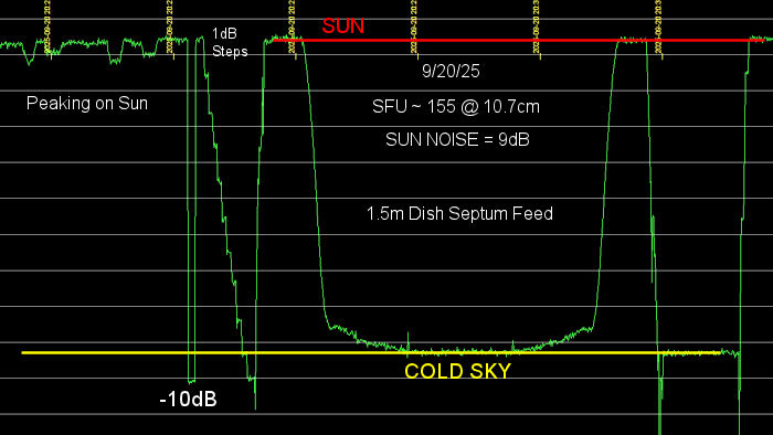
While it's early days, Currently both the copper foil and all-aluminum feeds, with square to round flares, seem to perform equally well.On 09/20/25 I measured around 9dB sun noise from both feeds, with the copper foil clad feed perhaps being slightly better by a few theths of a dB on some measurement sequence. The average 10.7cm SFU was around 155 at this time.
In a series of measurements around 9/26/25 through 9/28/25 I measured an average sun noise of 9.9dB, with numbers from 9.8dB to 10.1dB using the copper foil septum with flare, The sun was quite stable at a 10.7SFU around 155 over this time period. At this point the feed position had been optimized. The all-aluminum feed showed slightly lower sun noise at around 9.5dB and I have not worked on the feed to see if this can be improved.
At this time I was seeing a sun noise Y-factor or around 16.5dB on my 3.1m dish. That would make the 3.1m dish about 7.5dB better, which is not unreasonable. Based on area alone it would be expected to be about a 6.5dB difference, but the larger dish has a more efficient feed with a choke.
Here is a screenshot of LiveCQ, where I was calling CQ with the 1.5m dish, the copper clad feed and I had around 100W at the feed.
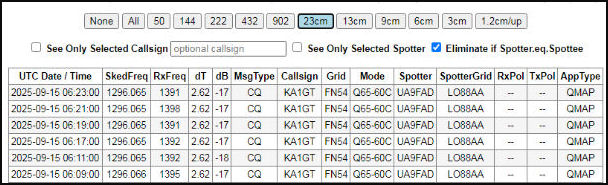
UA9FAD has a 3m dish with an f/d of 0.28. He was apparently copying my signal at around -17dB according to his LiveCQ report. That's not bad if the reports are accurate!
On the Rx side of things, again with the copper clad feed: Series of decodes of KB2SA running ~900W to a 1.9m dish:
* 044700 87.322 85.2 2.59 -15 30B CQ KB2SA DM13
* 044800 87.319 85.2 2.59 -15 30B CQ KB2SA DM13
* 044900 87.313 85.8 2.59 -15 30B CQ KB2SA DM13
* 045000 87.308 85.8 2.59 -14 30B CQ KB2SA DM13
* 045100 87.305 86.4 2.59 -14 30B CQ KB2SA DM13
And one decode on 3.1m dish * 045200 87.299 85.8 2.59 -7 30B CQ KB2SA DM13
The decodes run around 7.5 dB weaker than with my 3.1m dish, which is again quite good given that the 3.1m dish uses a more complex feed with a choke.
Note that Circular polarization axial ratios have not been measured It can be very tricky to get accurate numbers, but the feeds have performed well in on-air testsSee Circular polarization and Axial Ratio for more on axial ratios and associated losses.
Additional information
Gene, KB7Q, has been doing extensive testing with his 1.5m dish and the lightweight OK1DFC feed. See https://kb7qgrid.blogspot.com/. In general my results have been at least equal to what he is seeing, at least on Rx. I have not done extensive Tx testing yet, but in the tests I have done, performance seems good.This dish and at least the copper foil and aluminum feeds seem to be quite capable of working a decent 3m dish stations using Q65-60C using only 100W at the feed. The dish profile is is very accurate (all the way to 10Ghz), so it's just a matter of optimizing feed performance, and that's something several stations are looking at.