.jpg)
Circular Polarization and Axial Ratio
Circular polarization is used by almost all 23cm EME stations. It eliminates the need for rotation of linearly polarized antennas to match any geometric polarization shifts (Dpol) due to the location of the stations on earth and any Faraday rotation (which is actually very small at 23cm).
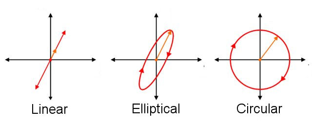
Perfectly circular polarization is hard to generate. The measure of circularity is called the axial ratio. In theory, this can be measured by receiving a circularly polarized signal on an linearly polarized antenna, then rotating either one and looking at the ratio of the maximum signal strength to the minimum signal strength. If there is no change at all in the signal strength as an antenna is rotated, the ratio is equal to 1. Expressed in dB this corresponds to a 0dB axial ratio. If the signal maximum is twice as strong as the signal minimum, the ratio is 2:1, which is 3dB. If the signal strength ratio is 10:1 then the axial ratio is 10dB.
Actually measuring axial ratio (of a feed) is another matter. There are numerous pitfalls which can create errors. Any multiple reflections can screw up the measurements, as can the distance between the antennas, any rotational asymmetry and countless other factors can introduce errors. Measuring axial ration sounds easy, but it isn't. Doing the measurements in an anechoic changer helps a lot, but unless that's your job, you are unlikely to have access to an RF anechoic chamber! It can be done on an outdoor range using a rotating dipole to measure signal strength from a circularly polarized source at different angles, but you have to be pretty careful and making accurate and repeatable measurements is not as easy as it sounds!
There are potentially other ways than rotating dipoles to indirectly or directly measure or calculate axial ratio, but that's something for future investigation. There's often an indirect relationship between isolation and axial ratio, where septum designs that provide higher isolation also tend to produce lower axial ratio. Though the two are not directly connected (there isn't a 1:1 correlation), a design which optimizes isolation also tends to give a higher axial ratio.
Pretty much any feed designed for circular polarization will not have an axial ratio of 0dB. They are all elliptically polarized to some extent. Good feed probably have an axial ratio in the 1 to 2dB range. Many may be closer to 3 or 4dB. A few may be even more elliptical. It all depends on the design and how well (accurately) they are built. Any asymmetry in the waveguide tends to give a lower axial ratio.
It should be noted also, especially in the context of lunar reflected signs, that while reflection from a smooth, infinitely large, conductive plane gives perfect conversion of RHCP (right hand circular polarization) to LHCP (left hand circular polarization), a 180 degree phase shift, reflection from the rough surface of the moon does not. There is some polarization scrambling, turning some of the incident CP energy into reflected linearly polarized energy and even some CP of the opposite sense. There is not a lot of polarization scrambling (especially from the center of the lunar dish), but there is some. So perfect CP sent out doe not come back as a perfect, 100%, conversion to the opposite CP direction.
Another point to be aware of is that the axial radio of the CP coming from your feed may not be the same as the axial ratio after reflection from the dish. This is almost impossible to measure, so even if you did measure your feed with a high degree of accuracy, you can't be sure your transmitted signal will have exactly that axial ratio!
Why does axial ration (ellipticity) matter, and does it matter?
Ellipticity matters because it can give rise to cross polarization loss when the axes of ellipticity are not aligned. For example if two stations have signals with a 3dB axial ratio, the signal loss due to polarization mismatch can range from 0dB, if the axes of both ellipses is perfectly aligned, to about 0.5dB if the axes ate orthogonal (i.e. at 90 degrees to each other). With axial ratios of 6dB at both ends of a QSO, maximum possible loss is around 2dB (minimum would be 0db). If one station has perfect circular polarization and the other has an axial ratio of 6dB, maximum loss drops to around 0.5dB.
The good news is that as long as the axial ration of both stations is less than 3dB, the signal loss will be less than 0.5dB, so striving for a perfect axial ratio of 0dB doesn't get you all that much (though every little hold on EME!).
The both good and bad news is that you have little or no idea what your actual axial ratio is, nor do you know what the axial ratio of your DX partners, nor do you know the orientation of the major axes of elliptical polarization at each end of the QSO. Plus you don't know how depolarizaion is taking place on reflection from the moon. While reflection from a smooth reflecting surface of a LHCP wave at normal (i.e. 90 degree) incidence gives an RHCP wave, reflections at other angles and from rough surfaces does not. So predicting exactly how much you actually gain or loose by neither end of a link actually being circular is difficult. And it will change with Dpol (geometric polarization rotation), which changes with time. There are usually too many variables and too many unknowns to do the calculation actual loss between any two stations at any particular time.
IMPORTANT NOTE Sun noise (or moon noise or ground noise)tells you nothing about axial ratio. The RF emission from the sun (or moon or ground)isn't polarized, so where you measure it with circular, elliptical or linear polarization, you (should) get the same result. Sun noise tells you about the system noise figure and the dish gain and efficiency, but it can't tell you anything about the polarization characteristics.
But does it REALLY matter and should I worry about it...

Beware of the Rabbit Hole
It probably doesn't matter very much in the real world. If your station performance is bad, and by bad I mean it's 2 or 3dB worse than it should be when you compare it with other stations using a simuilar antenna and power, you have more important (and easier to change) things to worry about than the axial ratio of your feed. On the other hand if you are striving for the last 0.1dB of signal and you already have good performance than maybe axial ratio is something to think about - but remember that most of the stations you work won't have perfect CP. The rabbit hole is there if you want to deplore it. The bottom line conclusion is that, on average, it's better if your axial ratio is low no matter what the Dx axial ratio is. You will gain more often than you will lose, and when you lose you won't lose much. But typically we are talking about differences of less than 1db, often less than 0.5dB.
What can we easily measure that might be of interest?
One thing we can (relatively) easily measure that might be of some interest is the ratio of power between LHCP and RHCP from an EME signal. Given this ratio you can calculate how much power you are losing due to polarization mismatch. It won't tell you where the loss is occurring (your system, the Rx system or the lunar reflection), but it can tell you how strong the signal would have been if everything was perfect!
The reasoning goes as follows. Assuming you station has a feed that is equally efficient at converting RF power to signal strength on both the LHCP and RFCP ports, then whatever EME signal is collected by the antenna and delivered to the feed will appear at either the CHCP port (normally the Rx port) or the RHCP port (normally the Tx port). So if you know the total power, and you know how much power you are receiving on the normal Rx port, you can then calculate the amount of power which is being lost to the Rx port.
So, for example, you see 10x as much power on the LHCP (Rx) port as you do in the RHCP (Tx) port, then you know that for every 100 "units of power' on the LHCP port, there are 10 "units of power" appearing at the RHCP port, and that power is lost to you. So you are seeing 100 out of 110 "units of power" or 100/110 = 90.91% of the total power. This corresponds to about a 0.4dB loss of signal. Ideally the unused port should be terminated with a 50 ohm load so that power directed to it is absorbed rather than reflected back. Also the system should be symmetrical with respect to the two ports, i.e the loss ahead of the LNA should be the same for the Rx port as the Tx port. If it isn't the measurement analysis becomes more complex.
Here's a graph of signal loss vs. measured difference in LHCP vs RHCP power difference. This is theoretical and assumed the incoming signal is LHCP with an infinite axial ratio. This will not be the case in real life, but the real situation is too complex for a simple plot!
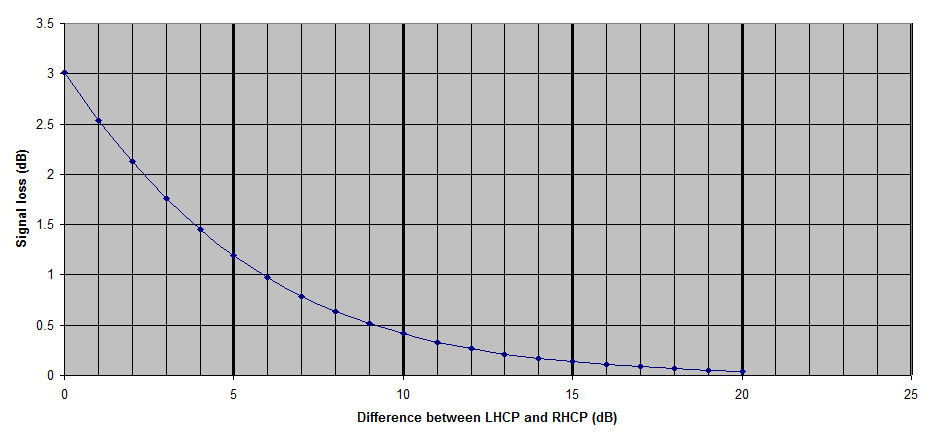
So you can see, for example, that if the signal you are receiving is linear (i.e. the Axial ratio is 0dB), then you get the expected 3dB loss). If the difference is 10dB or more, then you lose less than 0.5dB of the incoming signal energy at the desired port (Rx port, LHCP). Remember, these are theoretical results for receiving perfectly CP transmissions, but they give a fair indication of what what you might expect to find for at least some "real world" situations.
What happens in the real World?
It would be quite interesting to look at the SNRs of decodes of the same station using the LHCP and RHCP ports of an EME receiving system. If done for enough stations under enough different conditions it might be possible to draw some conclusions from the data.
The "real world" complication is that the incoming signal will not be RHCP with an zero dB axial ratio. For one thing the Dx station is VERY unlikely to be transmitting perfect CP. In practice this is very difficult, even for professional systems designed to be as close as possible to a 0dB axial ratio (e.g. satellite to ground transmission). They are usually in the 1dB to 2dB axial ratio range. For amateur 23cm EME stations I suspect very few are better than 3dB, and some may be as high as 6dB. Not only will the Dx station have some degree of ellipticity, you will too. Again I suspect few stations are better than 3dB. Maybe some as as good as 2dB - but you don't know who they are. Then there is the fact that even if you know your elipticity and the Dx station ellipticity, you probably don't know the inclination of the major axis of the polarization ellipse at either end. If you and the Dx station have matched ellipticity and major axis inclination, the loss between you will be 0dB - but only if Dpol (geometric polarization rotation cause by the path geometry) is zero. If the major axes of ellipticity are crossed and the axial ration of both stations is 3dB, there will theoretically be a 0.5dB loss between them. If one station is perfect and the other has an axial ration of 3dB, loss will be around 0.1dB.
So the best you can do for the real world situation is to calculate the maximum and minimum loss between two stations of known ellipticity (Axial Ratio), and this doesn't include any depolarization of the signal when it reflects from the moon - which we know does happen.
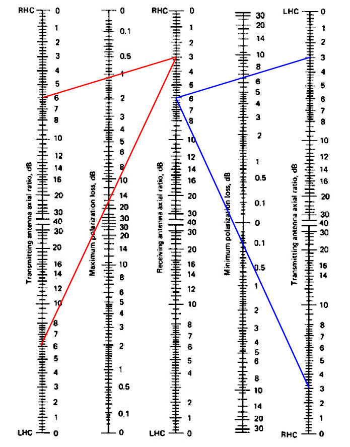
The nomogram below is quite useful for estimating loss due to ellipticity when the axial ratios are known. If one has an axial ratio of 3dB and the other has an axial ratio of 6dB, the maximum loss due to polarization between those two stations will be around 1.1dB. The minimum loss will be around 0.1dB. On the other hand if one station was using LHCP and the other was using RHCP, the minimum loss between then would be 7dB and the maximum loss would be around 16dB.
Clearly interpreting signal strengths for LHCP and RHCP decode strengths is not simple since you probably don't know your axial ratio or major axis angle, and you don't know those parameters for the Dx station either! Plus there's probably a little bit of loss from polarization scrambling by the lunar reflection. If one station was known to have a very low axial ratio, it might be possible to sue them as a "standard" signal. However since we no longer have a 23cm EME beacon, we no longer have the change that a beacon (with known axial ratio and major axis angle) could be used :(
Before making any LHCP vs RHCP measurements (again with the unused port terminated by a 50 ohm load), it's a good idea to calibrate your system by measuring sun noise on both ports. Sun noise (as far as EME with amateur dishes goes) is unpolarized - or you can think of it has having equal polarization of all types - so it should be the same whether you measure it using RHCP, LHCP. elliptical or any angle linear polarization. If you see a different level of sun noise on LHCP and RHCP then either you aren't using quite the same Rx system (maybe a longer length of coax from the LNA to one of the ports) or your feed is somewhat more efficient on one CP direction vs the other CP direction. In either case, the sun noise measurements can be used at add a correction factor to the decode strengths at the two ports.
If you consistently see only a few dB difference between LHCP and RHCP on multiple stations at multiple times, you probably have a problem. I would expect to see an average of at least 10dB and higher numbers at times, depending on the difference between the alignment of the major axes of the two elliptical polarizations (assuming axial ratios are always >0dB).
If you do make any comparisons of decodes using LHCP and RHCP ports, I'd be interested in the results. I'm in the process of making measurements, but it's too early to make any sort of report - or draw any conclusions other than it is quite an easy measurement to make once you have it setup with relays to do the switching. Doing it by hand works, but it's a bit slow!
References
For a much more detailed look at circular polarization with respect to EME station feeds and dishes please take a look at this informative article Circular Polarization and Polarization Losses by Rastislav Galuscak - OM6AA and Pavel Hazdra
Also of interest is Circularly Polarized Antennas Explained, Without The Math by Glenn Robb, Principal Engineer, Antenna Test Lab Co.
Paul Wade looks at the effect of dimensional variations in septum feeds an their influence on Axial Ratio here: Septum Feeds - Tolerances and Sensitivity by Paul Wade W1GHZ