.jpg)
Attenuator mismatch losses
One of the best ways of measuring sun noise is with the use of a step attenuator in the signal path. This can eliminate errors due to non-linear amplification stages which can result in gain compression (or less typically gain expansion). If an accurate step attenuator is used to reduce the level of noise from the sun down to the level of the background noise (cold sky), the attenuation value is the correct Y-factor sun noise, whether the system response is linear or not.
HOWEVER, this is only true if the impedance the attenuator is designed for is the same as the impedance of the line into which it is inserted. This may not always be true. For example if the attenuator is placed after an LNA but ahead of the input to an SDR, even everything may be nominally 50 ohms, it may be. What the attenuator sees at its input and output would depend on the length of the actual output impedance of the LNA (or last amplifier in the chain) and the actual input impedance of the SDR, with both possibly modified by the length and attenuation of the (50 otm) coax connecting them to the attenuator.
Unless otherwise specified, almost all attenuators are designed and calibrated for use in 50 ohm line. If it doesn't see 50ohms at the input and output, the attenuator calibration will not be correct. So how do you ensure that the input an output see 50ohms (or something very close to it?
The simple answer is that you use a 50ohm impedance fixed attenuator before and after the step attenuator. These is sometimes known as "pads", "masking pads", or "matching pads". Typically 3dB pads are used as a compromise between adding loss and eliminating mismatch. If the additional loss is likely to affect the system noise figure when used between and LNA and receiver, you can add a small, low gain, low noise amplifier head of the attenuator system. It only needs enough gain to compensate for the additional fixed attenuators. See, for example Fixed Attenuators Help Minimize Impedance Mismatches - minicircuits
Here's an illustration of this idea:
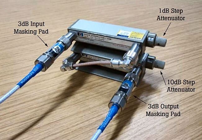
Reproduced from https://www.allaboutcircuits.com/ (see reference link below)
As you can see the attenuation chain is (1) A 3dB pad, (2) a 1dB step attenuator, (3) a 10dB step attenuator and (4) a 3dB pad.
If you measure sun noise Y-factor with the 3dB pads in place and without them, and you see no difference, then you were operating the attenuator in a matched 50 ohm system. However, if you see a different Y-factor (and you are sure the added attenuation is not changing your system noise figure), then the reading with the 3dB pads in place is more likely to to closer to the true Y-factor,
References
A good reference for this is Mismatch Loss and Mismatch Uncertainty Via Attenuators and Statistical Models
Also instructive is Pi-pad Attenuator Tutorial for Passive Attenuators