.jpg)
Measuring circular polarization losses in EME
https://jemengineering.com/blog-intro-to-antenna-polarization/
If you have ever wondered how much signal you are losing to due to circular polarization issues (Axial ratio, cross polarization etc.), here's one possible way to estimate your losses.
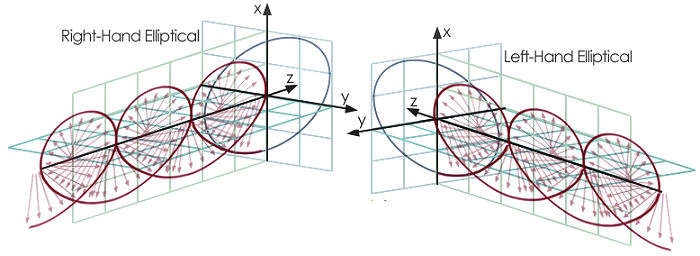
All polarization states, from linear through elliptical to circular can be considered (mathematically) as a superimposition of left and right handed circular polarization. The degree of ellipticity (which includes linear) and the major axis inclination angle are a function of the magnitude and phase of the superimposed left and right handed CP components. If the magnitudes are the same, the resulting polarization appears as linear polarization.
You can also consider all polarization states as a superimposition of orthogonal linear polarization, but for this article it may be easier to think of things by using the circular polarization model. The superimposition of states is just a way of thinking about the magnetic and electric field components of the (single) propagating electromagnetic wave
Given these principles, it follows that for circular polarization, such as that used for EME communication at 1296MHz, If you measure the power in the Left Handed Circular Polarized (LHCP) component of the signal and in the Right Handed Circular Polarized (RHCP) component of the signal, you can determine how much of the desired signal (LHCP for EME Rx) is being lost into the undesirable component (RHCP for EME Rx).
For example, if you look at an EME signal and find that it measures -10dB when decoded at the LHCP (Rx) port of a septum feed, and then you look at the signal at the RHCP (Tx) port of the feed and find that it measures -16dB, then you are seeing a 6dB difference between the ports. So in this case, the desired signal at the Rx port has 4 times the power of the undesired (lost) signal as measured at the Tx port. So you only see 4 "power units" out of the total of 5 "power units". If those 4 "power units" correspond to -10dB, all 5 "power units" would correspond to about -9db, so you would have lost 1dB of signal (10*log10(5/4)) to the orthogonal polarization mode. Whatever caused polarization to shift from the desired 100% LHCP circular to other modes (which can be considered as elliptical, RHCP or linear), resulted in 1dB loss of signal (and hence decode sensitivity) at the Rx port.
What causes this shift from circular to elliptical polarization?
There are a number of things that can modify circular polarization. First, no circular polarizer, including septum, is perfect. Even in theory, for a perfect circularly polarized septum feed, it would only be perfectly circular on axis (boresight). When a feed is used on a dish the geometry can result in some degree of polarization modification (Xpol or cross polarization). This appliers at both the Tx and Rx ends of any communication link. In addition, some degree of polarization scrambling can occur for anything but normal (90 degree incidence) reflection from a plane reflector - and the moon is not a plane reflector. It's rough, the reflection can come from the center of side of the visible disk. So EME signals will, in practice, always suffer some loss due to the fact that the Tx and Rx signals will not be perfectly circular.
How much loss are you suffering?
This is relatively easy to measure with any EME system if you make some small changes to your RX configuration. You need to measure the signal strength at both the normal Rx port (LHCP) and at the port you normally use for TX (RHCP).
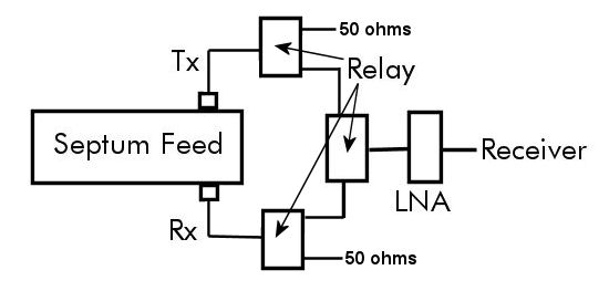
Something like this setup might be good, but it requires multiple relays. Even better might be replacing the 50 ohm loads with the actual Tx coax connetion, but doing that automatically would require even more relays!
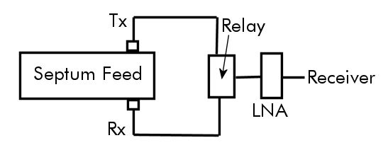
You can simplify this and still get potentially useful results (as shown below). However, be aware that the termination on the unused port will have some effect on isolation and axial ratio. If you wanted highly accurate estimates of loss, you might need to have the same impedance on the port on which you are not receiving as you do in your normal EME operation.
Most systems will have an isolation relay which switches the input to the LNA from the RX port to a 50ohm load. Most systems will have (or should have) the ability to do this switching manually in order to measure the ratio of sky noise to 50ohm noise (an important parameter in system optimization). So you simply remove the 50 ohm load and replace it with a connection to the Tx (RHCP) port. The you can switch between LHCP (rx port) and RHCP (Tx port) and compare the decode strength of a signal (e.g. a station calling CQ) on the two ports. IMPORTANT - to make the measurements easier and avoid the need for corrections, the connection the both ports from the relay should be as similar as possible in terms of loss. That ideally means the same length of the same type of coax with the same connectors and a minimum of adapters. So the setup would look something like this:
On any non-polarized noise source, such as sun noise, the signal should be the same on both ports. If it isn't then you either have to better balance the relay to port connections or make mathematically based corrections because you really you don't want to compare SNR values, what you do want to compare S (Signal values). If N is the same for both ports, then the difference in signal strength is the same as the difference in SNR values. However if the noise is only slightly different, then you can just add the noise difference in the SNR values. So if you have 1dB more noise when receiving on the Tx (RHCP) port than when receiving on the Rx (LHCP) port, and you measure -4dB on the Rx port and -12 on the Tx port, that's a difference of 8db in SNR values. But since the noise level on the Tx port is 1dB higher, the actual signal difference would be approximately -7dB. So rather than an 8dB difference in SNR, there's actually just a 7dB difference in signal strength. The reason it's a slight approximation is because it's likely that the port showing higher noise has addition loss in it's connection to the relay and that loss not only generates noise but also attenuates signal. Typically though it's likely to only be a few 1/10s of a dB if it's due to cable or connector losses.
The following plot convert the observed difference in the SNR for the two ports to the loss you are seeing on the desired signal:
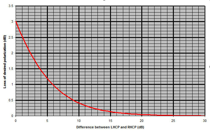
So a difference of 9dB corresponds to the loss of about 0.5dB in decode sensitivity, while 10dB difference is 0.4dB loss and a 13dB difference corresponds to a 0.2dB loss. You will see different differences on different station which will depend on your polarization, circularity and major axis inclination as well as those of the Dx station, and Dpol (geometric polarization rotation of the path) may also have some effect. The loss is a function of the whole link between you and the Dx station. It's not a loss just due to your station. Your station may be perfect (though that's probably unlikely!).
What should you expect to learn and see from the measurements
First, a single measurement just tells you how much signal you are loosing due to polarization mismatch under your measuring conditions. Even at best it doesn't tell you what your polarization is. It doesn't tell you what the Dx polarization is either. If either station is elliptical it doesn't tell you the ellipticity or how well your major elliptical axes are aligned. If doesn't tell you what your feed polarization is or how the much Xpol is introduced by the dish. All you see is the result of all this, not the mechanisms involved.
It's it's hard to say exactly what you should expect to see because it depends on your measurement configuration and both your station and the DX station you are listening to. Overall, I would say that if you frequently see 6dB or less difference, then your polarization might not be as circular as it could be and you could be losing 1dB of decode sensitivity. If you see an average of about 10dB difference then you'd only be losing about 0.4dB sensitivity and I suspect that's about normal. I'd be surprised if you saw an average as low as -16dB which would correspond to a loss of only 0.1dB sensitivity compared to "perfect". Note that in the case where the power at the RHCP port is the same as that at the LHCP port, i.e. the difference is 0dB, results in 3dB loss. That is the well known theoretical loss when you receive a linearly polarized signal (H, V or at any angle) on a CP antenna (LH or RH.
There aren't a lot of statistics to go on so it's hard to say exactly what is "normal". If you do make measurements like this I'd be interested in hearing your results.